Introduction to Variable Frequency Drives
Variable Frequency Drives (VFDs) represent one of the most significant innovations in modern electrical engineering, transforming how we control electric motors across industries. At the core of every VFD lies a fascinating energy conversion process from AC to DC to AC that enables precise control of motor speed and torque while delivering substantial energy savings and performance improvements.
This comprehensive guide will take you on a detailed journey through the VFD working principle, explaining each stage of the conversion process, the key components involved, advanced control methods, and practical applications that make VFDs indispensable in today’s industrial landscape.
If you’re new to Variable Frequency Drives, check out our comprehensive introduction: What is a VFD? Complete Guide 2025.
The Basics: What is a Variable Frequency Drive?
Definition and Core Function
A Variable Frequency Drive (VFD) is an electronic device that controls the speed of an AC motor by varying the frequency and voltage of the power supplied to it. Unlike traditional fixed-speed control methods, VFDs offer continuous, precise adjustment of motor speed to match actual load requirements.
The Fundamental Principle
The operation of a VFD relies on a fundamental electrical principle: the speed of an AC induction motor is directly proportional to the frequency of the power supply. This relationship is mathematically expressed as:
1
| N = (120 × f) / P × (1 - s)
|
Where:
- N = Motor speed in revolutions per minute (RPM)
- f = Frequency of the power supply in Hertz (Hz)
- P = Number of motor poles
- s = Slip (typically 2-5% for induction motors)
By controlling the frequency (f), a VFD can precisely regulate the motor’s rotational speed across a wide range.
For a more beginner-friendly explanation of VFD operation, visit our guide: VFD Working Principle Complete Guide for Beginners 2025.
The AC-DC-AC Energy Conversion Journey
The heart of a VFD’s operation is a three-stage energy conversion process that transforms incoming AC power into precisely controlled AC output:
Stage 1: Rectification (AC to DC Conversion)
The first stage of the VFD working principle involves converting the incoming alternating current (AC) from the power line into direct current (DC).
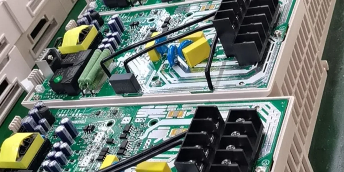
Rectifier Circuit Components
- Diode Bridge: A full-wave rectifier composed of six diodes arranged in a three-phase bridge configuration
- Power Diodes: Allow current to flow in only one direction, effectively converting the three-phase AC into pulsating DC
- Power Factor Correction (PFC): Optional circuitry that improves the drive’s power factor and reduces harmonic distortion
Rectification Process
- Three-phase AC power (typically 200V, 400V, or 480V) enters the VFD
- The diode bridge rectifies each phase of the incoming AC waveform
- The result is a pulsating DC voltage with a frequency of six times the input frequency (300Hz for 50Hz input or 360Hz for 60Hz input)
- The pulsating DC contains significant ripple that must be smoothed before the next stage
Stage 2: DC Link (Energy Storage and Smoothing)
After rectification, the pulsating DC is processed through the DC link, which serves as an energy storage and filtering system.
Key DC Link Components
- Capacitor Bank: The primary component that smooths the pulsating DC voltage
- DC Bus Capacitors: Store electrical energy and provide a stable voltage source
- DC Link Inductor: Optional component that provides additional filtering and can help reduce harmonic currents
- Brake Chopper Circuit: Allows for energy dissipation during regenerative braking
Function and Operation
- The capacitor bank charges and discharges to smooth out the DC voltage ripples
- Energy is stored in the capacitors to maintain voltage stability during transient conditions
- The DC link provides a consistent voltage source for the inverter stage
- During motor deceleration, regenerative energy flows back to the DC link, which can be dissipated through braking resistors or returned to the power grid in regenerative drives
Stage 3: Inversion (DC to Variable Frequency AC)
The final and most sophisticated stage of the VFD working principle is the inversion process, where the stable DC voltage is converted back into AC power with precisely controlled frequency and voltage.
Inverter Circuit Components
- Power Semiconductor Switches: Typically Insulated Gate Bipolar Transistors (IGBTs) or Metal-Oxide-Semiconductor Field-Effect Transistors (MOSFETs)
- Gate Driver Circuit: Controls the switching of the power devices
- PWM Controller: Generates precise switching signals to create the desired output waveform
- Output Filter: Optional components that improve waveform quality
Inversion Process and PWM Technology
- The DC voltage from the DC link is applied to the inverter bridge
- The IGBTs rapidly switch on and off (typically 2-20 kHz) using Pulse Width Modulation (PWM)
- By varying the width and timing of the pulses, the inverter creates a waveform that approximates a sine wave at the desired frequency
- The output voltage is controlled proportionally with frequency to maintain a constant volts-per-hertz (V/Hz) ratio for proper motor operation
Pulse Width Modulation (PWM): The Heart of Modern VFDs
PWM is the critical technology that enables VFDs to create variable frequency AC power from DC. Here’s how it works:
- The PWM controller generates a reference sine wave at the desired output frequency
- This reference wave is compared with a high-frequency triangular carrier wave
- The intersection points determine when to switch the IGBTs on and off
- The resulting pulse train has varying widths that approximate the reference sine wave
- When filtered by the motor’s inductance, this pulse train effectively creates a sine wave current in the motor windings
Modern VFDs use sophisticated PWM techniques like space vector modulation (SVM) to improve output waveform quality, reduce harmonic distortion, and increase efficiency.
Advanced Control Methods in VFDs
Beyond the basic AC-DC-AC conversion, modern VFDs employ advanced control algorithms to optimize motor performance:
V/Hz Control (Scalar Control)
The simplest and most common control method that maintains a constant ratio of voltage to frequency to provide constant torque operation.
- How It Works: Maintains V/f ratio proportional to motor design (typically 4-7 volts per hertz)
- Applications: General purpose applications, pumps, fans, conveyors
- Advantages: Simple implementation, lower cost
- Limitations: Reduced performance at low speeds, less precise torque control
Vector Control (Field-Oriented Control)
A more advanced method that decouples the motor current into flux and torque components for precise control.
- How It Works: Transforms three-phase current into two orthogonal components (d-axis and q-axis)
- Applications: High-performance applications requiring precise speed/torque control
- Advantages: Excellent low-speed performance, high torque at zero speed, fast dynamic response
- Limitations: More complex implementation, higher cost, may require encoder feedback
Direct Torque Control (DTC)
An advanced control method that directly controls motor flux and torque without complex coordinate transformations.
- How It Works: Uses hysteresis controllers to directly regulate torque and flux
- Applications: Very high-performance applications requiring rapid torque response
- Advantages: Superior dynamic response, excellent torque control, no encoder required for many applications
- Limitations: Higher current ripple, more complex implementation
Key Components of a Variable Frequency Drive
Power Circuit Components
Input Rectifier
- Converts AC to DC
- Handles incoming power and provides protection against power quality issues
DC Link
- Stores energy in capacitors
- Provides stable voltage for the inverter
- May include inductors and braking components
Output Inverter
- Contains the power switching devices (IGBTs/MOSFETs)
- Creates variable frequency AC output
- Handles the output current to the motor
Control Circuit Components
Microprocessor Controller
- The “brain” of the VFD
- Executes control algorithms and manages overall operation
- Processes input signals and commands
Gate Drive Circuit
- Provides isolated signals to control the power semiconductor switches
- Ensures proper timing and protection for the IGBTs/MOSFETs
Protection Circuits
- Overcurrent protection
- Overvoltage/undervoltage protection
- Overtemperature protection
- Short circuit protection
- Ground fault detection
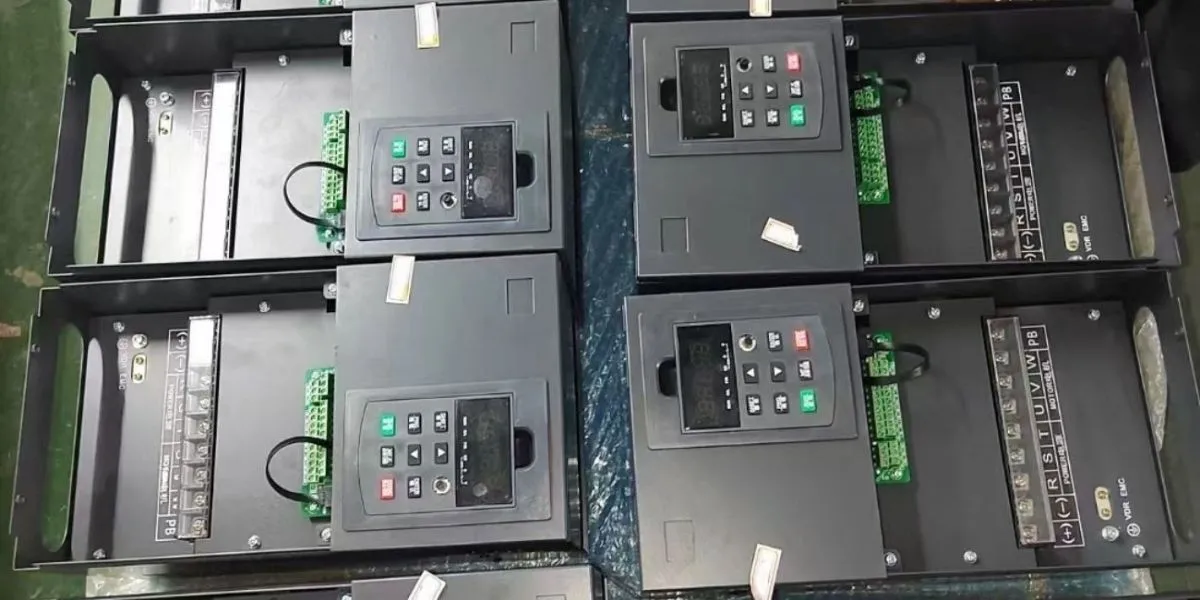
Interface Components
- Keypad/display for local programming and monitoring
- Digital and analog I/O for external control
- Communication ports for network integration
The Benefits of the AC-DC-AC Conversion Process
The sophisticated AC-DC-AC conversion process in VFDs delivers numerous advantages over traditional motor control methods:
Energy Efficiency Improvements
- Variable Speed Operation: Adjust motor speed to match actual load requirements
- Affinity Laws: For centrifugal loads, reducing speed by 20% can cut energy use by nearly 50%
- Elimination of Mechanical Controls: Replace inefficient throttling valves, dampers, and belts
- Power Factor Correction: Modern VFDs improve system power factor
Precise Control Capabilities
- Speed Regulation: Maintain exact speed regardless of load variations
- Torque Control: Provide precise torque for challenging applications
- Soft Starting: Gradually ramp up motor speed to reduce mechanical stress
- Controlled Stopping: Programmed deceleration to prevent equipment damage
Extended Equipment Life
- Reduced Mechanical Stress: Smooth acceleration/deceleration reduces wear and tear
- Lower Operating Temperatures: Running at reduced speeds generates less heat
- Fewer Start/Stop Cycles: Controlled operation reduces thermal cycling
- Protection Features: Built-in diagnostics prevent damage from electrical faults
- Improved Product Quality: Consistent speeds lead to more uniform output
- Process Flexibility: Quickly adjust to changing production requirements
- Automation Integration: Seamlessly work with control systems
- Data Collection: Monitor performance parameters for optimization
Applications Across Industries
The AC-DC-AC conversion technology in VFDs enables their use in virtually every industry:
HVAC Systems
- Variable Air Volume (VAV) Systems: Adjust fan speeds based on temperature and occupancy
- Chilled Water Pumps: Optimize cooling based on building demand
- Energy Recovery Ventilators: Control ventilation rates efficiently
Water and Wastewater Treatment
- Pumping Systems: Maintain constant pressure with variable demand
- Aeration Systems: Optimize oxygen transfer in biological treatment
- Mixers and Agitators: Precise control for various treatment processes
Manufacturing
- Production Lines: Synchronize multiple motors for coordinated operation
- Material Handling: Control conveyor speeds for efficient product flow
- Machine Tools: Provide precise spindle speeds for different operations
Oil and Gas
- Pipelines: Control pump speeds for varying flow requirements
- Compressors: Optimize based on pressure and flow demands
- Drilling Equipment: Provide precise control for extraction processes
Renewable Energy
- Wind Turbines: Optimize power generation based on wind conditions
- Solar Tracking: Control positioning for maximum energy capture
- Hydroelectric: Adjust generator speed for optimal efficiency
- Voltage Fluctuations: Can affect DC link voltage stability
- Harmonic Distortion: May require input reactors or filters
- Power Interruptions: Can cause nuisance tripping or equipment damage
- Three-Phase Imbalance: May reduce efficiency and increase heating
Motor Characteristics
- Motor Design: Different motors have varying performance with VFDs
- Insulation Class: Higher temperature ratings may be needed for VFD use
- Bearing Protection: VFDs can induce bearing currents requiring special protection
- Cable Length: Long motor leads may require output filters
Environmental Conditions
- Ambient Temperature: Affects cooling requirements and derating factors
- Humidity: Can cause condensation and corrosion issues
- Altitude: Reduces cooling efficiency at higher elevations
- Dust and Contaminants: May require special enclosures
Troubleshooting Common VFD Issues
Overcurrent Faults
- Causes: Motor overload, short circuits, incorrect acceleration times
- Solutions: Check load conditions, inspect motor windings, adjust acceleration parameters
Overvoltage Faults
- Causes: Regenerative energy during deceleration, power supply issues
- Solutions: Install braking resistors, extend deceleration times, check power supply
Overtemperature Issues
- Causes: Poor ventilation, ambient temperature too high, overloading
- Solutions: Improve cooling, reduce ambient temperature, check for overloading
- Causes: Incorrect V/Hz settings, poor power quality, motor issues
- Solutions: Verify parameter settings, check power supply, inspect motor
Future Trends in VFD Technology
Advanced Power Electronics
- Wide Bandgap Semiconductors: Silicon carbide (SiC) and gallium nitride (GaN) devices enabling smaller, more efficient drives
- Integrated Power Modules: Higher power density and reliability
- Advanced Filtering: Improved power quality with reduced components
- Bi-directional Converters: Energy recovery capabilities built-in as standard
Intelligence and Connectivity
- IoT Integration: Remote monitoring and control via cloud platforms
- Predictive Maintenance: AI algorithms to anticipate failures before they occur
- Digital Twins: Virtual models for testing and optimization
- Adaptive Control: Systems that automatically adjust parameters for optimal performance
Energy Efficiency Improvements
- Ultra-high Efficiency: Exceeding 99% efficiency in some applications
- Power Factor Correction: Nearly unity power factor operation
- Harmonic Reduction: Meeting the strictest standards without additional components
- Regenerative Capabilities: Recovering energy during braking for broader applications
Frequently Asked Questions About VFD Working Principle
Why does a VFD convert AC to DC and back to AC?
This conversion process allows for precise control of the output frequency and voltage. By first converting to DC, the VFD can then create an AC output with any desired frequency, which is not possible with direct AC-to-AC conversion using traditional methods.
How efficient is the AC-DC-AC conversion process in VFDs?
Modern VFDs typically achieve 95-98% efficiency. The losses primarily occur in the rectifier, DC link, and inverter components, but these are minimized through advanced semiconductor technology and circuit design.
What is the difference between hard and soft switching in VFDs?
- Hard Switching: Traditional PWM where semiconductor devices switch when current or voltage is non-zero, causing switching losses
- Soft Switching: Advanced techniques that ensure devices switch when either current or voltage is zero, significantly reducing switching losses and improving efficiency
Can a VFD damage a motor?
When properly applied, VFDs protect motors from damage. However, improper application can cause issues like:
- Insulation stress from high dv/dt (rate of change of voltage)
- Bearing damage from shaft currents
- Overheating from harmonic currents
These issues can be mitigated through proper motor selection, output filters, and parameter configuration.
To learn about the advanced semiconductor technologies that minimize these issues, read our guide: Advanced Frequency Converter Technologies 2025: IGBT & PWM Guide.
During regenerative braking, the motor acts as a generator, sending energy back to the VFD’s DC link. This energy can be:
- Dissipated as heat through braking resistors
- Returned to the power grid in regenerative VFDs
- Used by other motors in the system (in common DC bus systems)
- Stored in energy storage systems (capacitors or batteries)
Conclusion: The Engineering Marvel of VFDs
The variable frequency drive’s journey of energy conversion from AC to DC to AC represents a remarkable achievement in electrical engineering. This sophisticated process enables precise control of motor speed and torque while delivering substantial energy savings, improved performance, and extended equipment life.
From the rectification that converts incoming AC to DC, through the DC link that stores and smooths energy, to the precision inversion that creates variable frequency output, each stage of the VFD working principle plays a critical role in modern motor control.
As technology continues to advance with wide bandgap semiconductors, advanced control algorithms, and intelligent connectivity, VFDs will become even more efficient, powerful, and integrated into the industrial systems of tomorrow.
Whether you’re an engineer designing complex automation systems, a facility manager looking to reduce energy costs, or simply someone interested in the fascinating world of electrical engineering, understanding the VFD’s AC-DC-AC energy conversion journey provides valuable insights into one of the most important technologies powering our modern world.