
Introduction
Welcome to the comprehensive user manual for our Variable Frequency Drive (VFD) inverters. This manual provides detailed information on installation, operation, maintenance, and troubleshooting of our VFD products. Please read this manual carefully before installing or operating the equipment to ensure safe and efficient use.
Table of Contents
- Safety Precautions
- Product Overview
- Installation
- Wiring Instructions
- Operation
- Parameter Settings
- Maintenance
- Troubleshooting
- Technical Specifications
- Warranty Information
Safety Precautions
General Safety Guidelines
- Always disconnect power before installing, wiring, or maintaining the VFD.
- Ensure proper grounding of the equipment to prevent electric shock.
- Do not operate the VFD in explosive or flammable environments.
- Keep the VFD away from water, moisture, and direct sunlight.
- Allow proper ventilation around the VFD to prevent overheating.
Warning Symbols
Improper installation or operation may result in electric shock, fire, or equipment damage. Follow all safety guidelines provided in this manual.
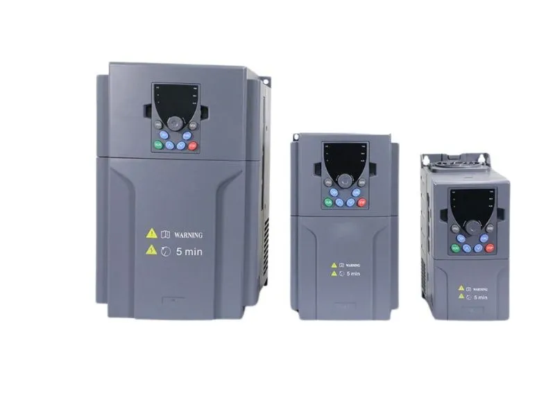
Product Overview
Models Covered in This Manual
- AC-Drive-1.5kW
- AC-Drive-2.2kW
- AC-Drive-3.7kW
- AC-Drive-5.5kW
- AC-Drive-7.5kW
Key Features
- Vector control technology for precise motor control
- Built-in PLC functionality for simple automation tasks
- Multi-speed operation with up to 16 preset speeds
- Modbus communication capability
- Overload, overvoltage, and overcurrent protection
- Compact design for space-saving installation
Installation
Environmental Requirements
- Ambient temperature: -10°C to 40°C
- Relative humidity: 5% to 95% (non-condensing)
- Altitude: ≤ 1000m above sea level
- Avoid locations with excessive dust, vibration, or corrosive gases
Mounting Instructions
- Ensure the mounting surface is flat, rigid, and capable of supporting the weight of the VFD.
- Mount the VFD vertically using the mounting holes provided.
- Allow minimum clearances:
- Top and bottom: 100mm
- Left and right: 50mm
- Front: 200mm (for maintenance access)
Wiring Instructions
Power Supply Connection
- Connect the input power (L1, L2, L3) to the R/L1, S/L2, T/L3 terminals
- Connect the ground wire to the PE terminal
- Use appropriate wire sizes based on the VFD rating
- Install a circuit breaker and isolation switch on the input side
Motor Connection
- Connect the motor leads (U, V, W) to the U/T1, V/T2, W/T3 terminals
- Ensure proper motor grounding
- For three-phase motors, verify the rotation direction after initial startup
Operation
Control Panel Functions
The control panel provides the following functions:
- Power ON/OFF button
- Run/Stop button
- Forward/Reverse button
- Speed adjustment dial
- Digital display for frequency, current, voltage, and fault codes
- Parameter setting buttons
Basic Operation Procedure
- Ensure all wiring is correct and secure
- Apply power to the VFD
- Set the desired frequency using the speed dial or parameter settings
- Press the Run button to start the motor
- Monitor the operation and adjust parameters as needed
- Press the Stop button to stop the motor
Parameter Settings
Frequently Used Parameters
| Parameter | Function | Factory Setting | Range |
|---|---|---|---|
| P001 | Maximum frequency | 60Hz | 0-400Hz |
| P002 | Minimum frequency | 0Hz | 0-400Hz |
| P003 | Base frequency | 50Hz | 0-400Hz |
| P004 | Acceleration time | 10s | 0.1-3600s |
| P005 | Deceleration time | 10s | 0.1-3600s |
| P006 | V/f curve selection | 0 | 0-5 |
Parameter Setting Method
- Press the MENU button to enter the parameter menu
- Use the ▲▼ buttons to select the parameter group
- Press the ENTER button to enter the parameter group
- Use the ▲▼ buttons to select the desired parameter
- Press the ENTER button to modify the parameter value
- Use the ▲▼ buttons to adjust the value
- Press the ENTER button to save the setting
- Press the MENU button to exit the parameter menu
Maintenance
Regular Inspection Schedule
- Daily: Check for unusual noise, vibration, or overheating
- Weekly: Clean dust and debris from cooling fans and vents
- Monthly: Check for loose connections and signs of corrosion
- Quarterly: Inspect cooling fans for proper operation
- Annually: Complete system inspection by qualified personnel
Cleaning Instructions
- Disconnect power before cleaning
- Use a dry cloth to wipe the exterior
- Use compressed air (max. 0.4MPa) to clean cooling fans and vents
- Avoid using water, solvents, or abrasive materials
Troubleshooting
Common Fault Codes
| Fault Code | Description | Possible Solutions |
|---|---|---|
| E.OC | Overcurrent protection | Reduce load, check motor and wiring |
| E.OV | Overvoltage protection | Check input voltage, reduce deceleration time |
| E.UV | Undervoltage protection | Check input voltage and power supply |
| E.OH | Overheating protection | Check ventilation, reduce load, clean cooling fans |
| E.SC | Short circuit protection | Check motor and wiring for short circuits |
| E.PH | Phase loss protection | Check input power phase |
Reset Procedure
- Identify and resolve the cause of the fault
- Press the RESET button on the control panel
- If the fault persists, disconnect power for 1 minute and reconnect
- For recurring faults, contact technical support
Technical Specifications
Electrical Specifications
- Input voltage: 380V-480V AC, 3-phase
- Input frequency: 50/60Hz ± 5%
- Output voltage: 0-Input voltage
- Output frequency: 0-400Hz
- Control method: V/F control, Vector control
- Rated current: See nameplate for specific model
Physical Specifications
- Enclosure rating: IP20 (Indoor use only)
- Cooling method: Natural convection + forced air
- Weight: See nameplate for specific model
Warranty Information
Our VFD products come with a standard 12-month warranty from the date of installation or 18 months from the date of manufacture, whichever comes first. The warranty covers defects in materials and workmanship under normal use and service conditions.
Warranty Exclusions
- Damage due to improper installation or operation
- Damage caused by accidents, misuse, or neglect
- Modifications or repairs by unauthorized personnel
- Use of non-genuine replacement parts
- Normal wear and tear
Last updated: December 15, 2023 Version: 2.1 Document Number: MAN-VFD-2023-01